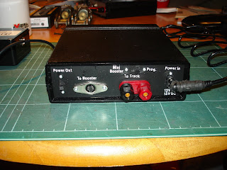
In my last blog entry, I showed my recently completed Merg CAN-CMD CBus controlled DCC Command Station. The Merg kit includes the PCB and all the components to populate the PCB. For future layouts I will probably just mount the PCB directly to a baseboard and hard wire it in. However, this first one I wanted to keep as a portable and flexible unit.This meant fitting it into a case with suitable sockets, switches and Led indicators.
I found a suitable case on Ebay made from black plastic with aluminium end plates and adequate size to take the PCBs and wiring inside.Drilling, cutting and filing all the holes in the aluminium end plates took three evenings to complete. The aluminium plates were then cleaned, sprayed black and lettered with Letraset rub-down lettering, and finished with some clear spray laquer.
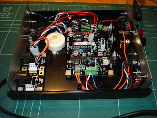
Inside the case is the CAN-CMD main circuit board and the CAN-TERM connector kit PCB with two RJ22 sockets. These can be used to plug in a CAN-USB computer interface, or the forthcoming CAN-CAB handheld controller, or to connect to a layout CBus as required.
The one panel has all the CBus related switches and connectors, and the two indicator LEDs. The green LED only lights up if the microcontroller program is running correctly. The Yellow LED lights up when in 'Mini-Booster' mode or flashes when programming locomotives or accessories decoders. The two RJ22 connectors previously mentioned are on this panel, along with two switches. One switches in a bus terminator resistor, required if this unit is at one end of a long Cbus, or used with just a CAN-CAB or CAN-USB. If this unit is connected to a layout CBus that already has terminators fitted then the inbuilt terminator can be switched out. The second switch allows this unit to supply 12V DC to power other CBus items, like the CAN-USB or CAN-CAB. Again, if connected to a layout Cbus that has a separate 12V DC supply, this can be switched out.
The other panel has a socket to connect the power supply, either 12V AC or 15V DC at up to 1 Amp.The screw terminals allow connection to either a programming track or a small layout if using 'Mini-Booster' mode. The mode of this output is controlled by the switch above. The 4-pin mini-Din socket will allow external DCC Boosters (another forthcoming Merg kit) to be attached if more than 1 Amp is required for a layout. The remaining switch controls 12V DC output the the external boosters if required.
Saturday 20 August 2011
Sunday 10 July 2011
A Bus for Freshwater
Not that sort of of bus - a layout control bus. DCC is really good for controlling trains, but is less suited for controlling points and signals and the like. A separate bus for operating accessories means that a short circuit on the track does not cause points and signals to change at random. The separate bus can also use systems that are more suited to train detection and route selection.
I initially joined Merg (Model Electronic Railway Group) in order to access their servo controller kits, for controlling points and signals. Having joined, I found out about their development of a layout control system based on the CBUS two-wire command bus. The CBUS protocol has been used in all new cars for a number of years, to reduce the complexity of the wiring loom, and increase the functionality. It is a fairly simple protocol, compared with TCP/IP as used by the Internet. The bus is used to join up various devices all over the car. It allows 'producer' devices (switches, or sensors for instance) to broadcast simple numbered 'event' messages over the bus. All the 'consumer' devices attached to the bus will see these 'event' messages, but certain devices will be setup to perform specific functions when specific events are seen. Thus a switch can broadcast an event which the windscreen wiper controller will act on to start the windscreen wiper motor. A rain sensor can be set up to broadcast the same event. It might also broadcast another event which would result in the headlight controller lighting the headlights. The CBUS is equally useful for controlling a layout. Control panel switches and train detectors can become 'producer' devices, and point motors, signal motors and mimic display panels can become 'consumers'. Because of the widespread use of CBUS in the automotive industry, the basic components required are readily available and low cost.
Last year, I purchased a couple of Merg kits, an eight input 'producer', and an eight output 'consumer'. I also picked up the experimenters kit, a small board with eight switches on that plugs onto the 'producer' kit, and a board with eight LEDs on that plugs into the 'consumer' kit. The Merg kits are designed to allow them to be 'programmed' using small switches that are part of the kits. The 'producer' can be told what events to broadcast for each switch operation, and the 'consumer' kit can be taught which events to listen for, and which LEDs to light or extinguish when the event is seen. The Merg kits were designed to use a 5VDC supply distributed from a power supply regulator on one of the kits, which required a 12-16V supply. I experimented with these modules, but did not get round to using them on Freshwater as deadlines approached, and a temporary 'traditional' control panel was built. I do intend to use CBUS eventually as it will allow simple route selection and some interlocking to be implemented.
The photo shows a 'producer' board on the left, with eight yellow switches on the experimenter board plugged on the end. On the right is a 'consumer' board, with eight red LEDs on the experimenter board plugged on its end. They are connected by the 2-wire bus (blue and white wires). The orange and black wires are the power supply lines. In the centre is a C-BUS connector board, and a power supply can plug into the lead coming down from the centre. I have modified these boards to run from a 12VDC supply instead of the 5VDC supply that the kits were originally designed for.
Over the last 12 months, more kits have become available, along with interfaces to a computer to simplify the programming of the modules. The computer interface also allows computer control of a layout, using suitable software like the freely available JMRI. The latest development from Merg is a DCC command unit and a hand-held controller. The CBUS is used for communication between the controller and the command unit. JMRI can also be used as a throttle connecting to the command unit via the CBUS.
So, to prepare for the DCC system, and use of the CBUS on Freshwater, I purchased the Merg kit for a CBUS to USB interface. This was initially built as per the instructions. It is designed to take a 5VDC supply. I therefore created a simple 5VDC regulator circuit on a small piece of veroboard, and mounted everything in a small black plastic case. A 4 way cable with an RJ22 type connector at the end that can plug into a Merg CBUS connector kit, comes from the box, connecting the two bus wires and the 12VDC supply into the box. A standard USB connector protrudes from the other end of the case.
Having a working USB interface, I set to building the DCC command station kit from Merg. This has been built as per its instructions. It is already designed to take an external 16VAC power supply, and can supply 12VDC to other devices on the bus.
The photo shows the USB interface box on the left, which connects to the USB port on a PC. It also plugs into the CBUS connector board and the bus then connects to the DCC command station board on the right, the red and black wires next to the bus wires have a socket for connecting the power supply. The red and black wires to the far right attach to the test track at the top of the photo. The white round object at the bottom right is a buzzer used as a short circuit warning. This setup now works, using a JMRI software throttle on the PC. I have also played with a Wi-throttle 'app' on an iPhone using a WiFi connection to the JMRI server on the PC.
Merg will very soon have a kit available for a hand held DCC controller that will plug directly into the CBUS connector board, and do away with the need for the USB interface and PC. Watch this space.
Sunday 6 March 2011
Bridging the Gap
Now I have taken on a new deadline for Freshwater, the 2mm Expo at Keighley, I am now motivated to get on with the scenics. First off, a bit of terra-forming. As I had some sheets of foam-board available, I thought I would use some to build up the contours. Most of the station area is flat, so it is only the river banks and the start of a small hillock behind the station that needed building up. When I have smoothed out the slopes, I intend to cover it with PVA soaked kitchen towel. I hope to avoid having to use much filler, as the board does twist and move a bit, and filler will probably crack and break up.
Only a small number of buildings are needed for the layout, so I want to avoid using kits (except for the ratio concrete platelayer's hut probably), and scratch build as much as I can. Starting with the basic civil engineering, I need a bridge over the tidal River Yar. I have not found any photos of the real bridge, so I need to freelance it. I would have liked to build a dainty little bridge with hand rails, but rail cleaning at exhibitions would probably destroy them. Therefore, I decided on a large girder type bridge, giving plenty of clearance for the tide to come in.
The main girder and end pillars were cut from a single piece of plasticard, then further layers of plasticard were added to build up the pier thickness. By using a single piece, the piers and girder will always be at right-angles to each other, and will not move when the bridge is fitted in place. Strips of thin plasticard have been added to complete the girder. In the photo, only the nearest girder is complete.
When the girders are complete and painted, they will be glued in place, and the abutments below the bridge will be completed in place. Brick paper will then be applied to finish off the abutments and piers. Hopefully, all will be complete next week. Then I can start on the platform. The original platform was brick edged, then it was extended using concrete panels, and then another extension was added with concrete pillars. Should be fun.
Subscribe to:
Posts (Atom)