Tuesday 30 August 2016

A busy evening with Camford Junction

A busy club evening, with Robin building more points for the TMD area, Graeme fitting point servos on the second board, and Pete and I painting track on the first board in preparation for ballasting.

So, for a change, some views of the tops of the baseboards.

The two scenic boards:


The first two crossovers:
and some of Pete's stock that will be running on the layout, one day:


Wednesday 24 August 2016

More wiring on Camford Junction

After a few club-nights the main line wiring on one board is finally complete. The amount of wiring would have been a lot less if we had gone for DCC, but I am the only member of the group with DCC fitted stock, and it is not of the right era for the layout, so I lost that battle.

The relays, controlled by Merg CBus modules, switch the various track sections between the 4 main line controllers. There are only 3 points on the main line on this board, controlled by the black Merg CBus CANSERVO8 module.

The wiring along the edge of the layout consists the 4 controller feeds, 12V and 5V power supplies and the CBus pair. The wiring down the other side of the raised section is the feed from the relays to the track sections. The expanse of virgin white board, where the documentation is laying, will be home to the MPD, and will be covered with servos and more Merg CBus modules eventually.

 Meanwhile, the second board has had most of its hardware fitted and will be ready for wiring up to commence while track laying for the MPD area can start on the first board. This board also has just 3 points on the main lines. The tie-bars have been fitted and the servos will be fitted next week, hopefully. Note, the elevated secondary main line diverges from the main, main line on this board, running along what will be filled, brick arches.

Wednesday 25 May 2016

What goes on below Camford Junction

Now that the elevated main line tracks have been laid, I wanted to make a start with the hardware and wiring below the baseboards before track laying in the lower  depot area started. Firstly, individual dropper wires were soldered to each separate length of rail, and pushed down through holes drilled in the baseboard. The dropper wires are single strands from a multi-strand cable. Each one is like a piece of fuse wire, but being just a couple of inches long has been found completely reliable on a number of 2mm scale layouts we have built.

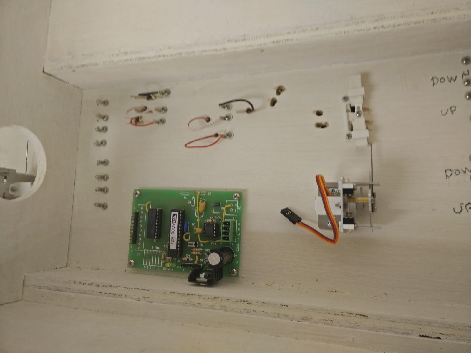
Below the baseboards, the dropper wires are joined to solder tags screwed to the woodwork. These will later be linked by proper, multi-strand hookup wire.


The photo also shows a cheap relay module found on eBay. These relays will be used to connect the four analogue controllers to the various track sections, dependent on the selected routes.

The points will be operated by cheap RC servos. These are mounted in aluminium 'Dingo' servo mounts, which allow the servo to travel fully while only moving the actuating wire a few millimeters. This is important for slow and quietly smooth movement of the point blades. The mounts also include micro-switches that can be used to switch the frog polarity and give position feedback to a control panel.

The under baseboard tie-bars I designed for this layout are 3D printed, and are now available from the 2mm Scale Association shop.


The layout will use the Merg CBus layout control bus (LCB) which is designed to reduce the amount of long runs of multiple wires, requiring only 4 wires between a control panel and the layout. Various actions, such as pressing a button, or a train being detected in a section, will cause numbered 'event' messages to be broadcast across the bus. Other modules will be taught to act on specific events, switching relays, moving servos, lighting LEDs, or whatever. There will still be a lot of wiring, but most will be short runs, contained within a single baseboard. The bus concept is also more flexible than conventional wiring, as modules can be taught to act on new events, or perform different actions for existing events, as the layout evolves. This photo shows a CANACC8 module (which produces 8 steady-state outputs) that will control the two relay modules. I still have to attach a CANSERVO8 module, that can operate up to 8 servos, but this will also operate some of the depot points, so I need to determine the best location for it to minimise the wire lengths required to the servos. Servos can jitter if they pick up electrical noise in their wires, especially with analogue locomotive control. Surprisingly, DCC locomotive control is not such a problem.


To assist with setting up and positioning the point tie-bars and servo mounts, this little servo tester I found on eBay has proved very useful. It can move the servo to its centre position at the push of a button, or you can use the knob to manually move the servo, or it can work automatically in 'windscreen wiper' mode.

So, next week, I can start adding some wires.

Friday 8 April 2016

Bognor Regis - Unfinished Symphony

As Alresford approached the end of it's exhibition life, and with a growing band of helpers at the Basingstoke and North Hants Model Railway Society, we started planning a more ambitious 2mm finescale layout. We narrowed down the prototypes to Eastbourne or Bognor Regis. We chose Bognor as it was closer to us, and would not require the curved baseboards that Eastbourne would require to do it properly.

The layout was 24 foot long (including fiddle yard) and 3 foot at its widest. There were 17 points and two double slips in the viewable area, and we photo surveyed about 120 buildings, or building groups that would have to be modelled. The layout sat on a tubular steel framework. The baseboards were timber frames with MDF tops. The board ends were drilled in pairs to align bolt holes, dowels and brass locators. All the track was built, laid and operational, and 20 odd buildings were completed, and the layout was exhibited a couple of times as a work in progress. It was lovely to see a 12 coach train snake into a platform across the pointwork.

Then disaster struck. The timber started to warp, and the board ends started resembling propelers. Members started drifting away, and in the end the layout was abandoned.

Here are some photos. More are in my Flickr album https://www.flickr.com/photos/ianm42/albums/72157666919743795


Monday 4 April 2016

Nostalgia Break

I stumbled across some scanned photos in one of the dusty corners of my hard drive, and thought I would share them. They are of the 2mm finescale layout 'Alresford', built by members of the Basingstoke and North Hants Model Railway Society in the late 1980's. Dave Harris, Clive White, the late John Moffat, and myself were the main driving force behind the production of the layout, although there were others, whose names I have sadly forgotten,  that provided some input.

It visited quite a few exhibitions in the first half of the 1990's, and appeared in the Railway Modeller magazine (with better quality photos than these).