Sunday 25 October 2009

First piece of track laid

There has been a bit of a pause in progress while constructing the track required. As I only have one evening a week to allocate to modelling at the moment, it has taken longer than I would have liked. I also found a new way of slowing up progress by deciding to try filling the insulation cuts in the copper-clad sleepers with milliput (after checking the gaps were actually insulated). With a spray of primer (after washing with Cif and a finger nail brush) they really do look better for being filled.

I also built some MERG servo control boards and a tester/programmer box, as I will be using servos to operate the points and uncoupling magnets. More on these subjects will come later, I hope.

Anyway, the first length of track to be laid is across the board join to the fiddle yard. I am trying out the easytrack brass sleepers for this. Six of these sleepers were soldered in with concrete sleeper profiled copperclad, and the whole lot primed. I had to smooth out my poor carpentry by planing the surface slightly, and digging out a little to cater for the brass sleepers being fractionally thicker than the copperclad ones. The whole length was fixed down with Araldite and weighted down overnight. This morning I have sawn the rails across the gap, and sawn the brass speepers in half to restore insulation between the rails. A little more Milliput filling is required before painting the sleepers, and ballasting.


The photo also shows some foamboard being used as a basis for the river banks. The river is still tidal here, so it will have steep, deep banks.

The first point will be situated just beyond the bridge, so I now have to decide on, and build the operating mechanism, more on that next time.

Friday 1 May 2009

Changing my Mind

Not a lot of visible progress for a while, but I have been beavering away building track. Having built a couple of points using the jig I have (equivalent to about 3 foot radius) I scanned them, and printed paper copies which were cut out and used for trying to mark out the track layout on the baseboard. Try as I might, I just could not get the track to match the original layout, with the outside slip. So, I decided to revise my plans, and follow the later track layout without the slip. This also means losing the locomotive facilities, but does reduce he number of points that need to be built. The revised layout plan is shown below:


I also used the scanned images to put together a template for the crossover at the buffers end of the platform road. With some care and attention, I managed to build most of it in the point jig, re-inserting the construction into the jig in different orientations a few times.


If I had realised that the jig is exactly the right width, I could have used it as a sawing jig for the full length sleepers. Note, I have not used chairplates for this layout in a bid to save time. Previously, when I have used chairplates, the daylight gap beneath the rail disapeared during ballasting anyway.

Here is the track built so far. Three more points and plenty of plain track needed for the layout board. More needed for the fiddle yard.


Having tried traversers, sector plates, turntable points and cassettes on previous layouts, proper points have proved to be the most reliable solution, albeit they take up a long length of the fiddle yard. I will be attempting a 4-way point for this fiddle yard. Wish me luck.

Saturday 21 March 2009

More Fresherwater Progress

After some consideration, I decided to change my mind about moving the road. Instead, I added a couple of pieces of wood below the baseboard ends to reinforce the cutouts for the river bed, and added the second cutout on the front edge. I also added four small squares of wood to make locating the trestles better defined. Both these additions can be seen in the following photo:


The photo also shows a brick holding down the river bed while the glue dries. Three layers of 5mm foam board were used to form the river bed, and the stream bed that runs along behind the platform. The ends of the river that pass over the board edges had the foam and the lower face removed, and will be glued to the woodwork separately (hopefully leaving the river surface smooth). The banks will be formed from more foam board later.

Saturday 7 March 2009

Baseboard progress

Another Saturday morning, and some more progress. The trestles I purchased cheap on the Internet turned up, and I have assembled them. They are just what I had hoped for, and make a steady, sturdy support for the layout, and adjust from really low (for a layout) to a bit too high.


The cabinet makers dowels and catches also turned up in the post, and so the fiddle yard board now connects to the layout. My poor carpentry skills let me down a bit, and I have ended up with a little step to be dealt with when track laying, but it should end up OK.


I scratched my head a bit over supporting the far end of the fiddle yard. The catches and dowels would not survive the stresses for very long, but the weight to be supported at the end of the fiddle yard is not very heavy. I did not want to resort to a leg, as it would not be adjustable in height like the rest of the layout. There was not really anywhere to mount a diagonal brace to, easily. I had an idea about cantilevering somehow. I found a suitable piece of timber about 5 feet long, and attached small pieces of timber at each end (see photo above). The centre of the timber rests on top of the trestle, and the attached pieces of wood hook under the layout and fiddle yard at each end (see photo below). It seems to work, but I might add some catches to hold it in place.


So, that is it for this week. The layout needs a backscene board, and I will put a safety fence around the fiddle yard. I also want to build boxes to protect the layout for transport and storage. All this heavy woodworking needs to be complete before track laying starts. I had better start building some track to lay.

Saturday 28 February 2009

More hacking at the baseboard

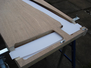
After last weekend's work on resizing the door, and making a cut-out area underneath the layout for the point mechanisms, etc, to go, this weekend's activity was a little less to do. The glue having set, all the edges were sanded down. Two cross members were screwed and glued across the underside. These will be used to locate the board on the leg trestles, but were also intended to strengthen the layout before the cut-outs for the stream and river Yar were made in the layout's top surface:

The rounded ends of the new cross members can be seen below the layout, about 4 inches in from each end. They also mean that the layout does not lie flat on the floor when off its legs, and can be picked up more easily.

The 6 inch grid has been drawn on the topside of the layout, and the trackplan sketched out on it. The locations of the strengthening timbers around the underside cutout have also be marked, to help me avoid them. The areas for the stream and river were then cut out with the jig saw and the cardboard lattice removed. The level of the river bed will not be the full depth of the door thickness. It will be as deep as the cutout in the edge timber.

I shied away from making a similar cutout in the timber at what will be the front of the layout. I decided, instead, to move the road bridge downstream a little so it covers the timber. I may change my mind again later, once I have completed the fiddle yard connection. Now, I can just await delivery of the leg trestles, and brass baseboard joining dowels. I intend to complete all the woodwork construction, including backscenes and transportation/storage boxes before starting any track laying.

Tuesday 24 February 2009

Time to throw my hat into the ring

Since the 2mm Scale Association laid down their Golden Jubilee Layout Challenge to build a layout of 9.42 sq. ft. or less in time for their 2010 Expo, I have spent a year and a half thinking about it, and now I have a year and a bit to actually build something.

The thinking bit was quite tough, coming up with criteria to be met by the eventual design, and then getting a design that met most of those criteria. The criteria included:

- max area 9.42 sq ft, of course
- maximum baseboard length, 5 ft (for transport)
- interesting to operate and view
- not too complex, given the time constraints
- Southern region, BR 1950's - 1970's
- based on a real location

Finally a suitable prototype presented itself, although it does require generous use of modeller's license. The location is the terminus at Freshwater on the Isle of Wight. Combining a scan of a large scale O.S. map onto the satellite photography of Google Earth, I found that it easily fitted on a 5 ft. by 1 ft 6 inch baseboard, with a fiddle yard of 2 ft 6 inches by 9 inches (total area 9.375 sq. ft).

The original track plan shows lots of interest, with the kick-back sidings and outside single slip. Unfortunately, the layout was rationalised between the wars, and the slip, and two sidings serving the loco facilities were removed, along with the short siding to an end loading bay. An extra spur from the run round, making 3 bufferstops by the station building was added though. For operating interest, all the track from both periods will be retained:


(the purple lattice is 6 inch squares)

To make it possible to extend the operating life of the line, and allow more variety of stock to be used, I have invented a new course of history. Following the war, it was decided to keep the Isle of Wight's rustic charm by banning all road improvements on the island, and restricting motor vehicle use to residents and local businesses. Money saved was put towards the Lymington-Yarmouth rail bridge/tunnel link. All the existing rail routes on the island were then relied upon to convey produce, supplies and holidaymakers. (Britain's version of NASA was based near Freshwater, and might have generated some traffic if it had not been abandoned).

The line from Yarmouth to Freshwater thus became a short branch, with direct trains from Newport and Cowes. Excursions from the mainland would need to reverse at Yarmouth. This new history and generous use of modeller's license means I wil call the layout "Fresherwater".

So much for the ideas, time for something practical. On a visit to the closing down sale at our local Trade Depot I found a pile of plain plywood doors for just £4 each. I felt sure I could do something with one of them, and for that price, I could just dismantle it and use the plywood. First, I would try to make use of the strength of the door's construction.

I started by cutting the door down to 5 ft. long. That is when I realised the faces were not ply, but MDF made to look like ply. However, I continued with my plan, and fitted a length of timber into the cut end, glued and clamped. Then the door was cut lengthways to bring it down to 1 ft. 6 inches wide, and another length of timber glued into the gap at the edge, to give the door its strength back again. The offcut from the end of the door was trimmed to 9 inches, and a length of timber glued in to form the fiddle yard.

Next, I drew out the layout (mirror imaged) to what will be the underside, to determine where point motors and uncoupler magnets will go. This area was then cut out, and the cardboard lattice strengtheners removed from inside the door. More timber framing is then glued in along the edges to return the strength. The photo shows the edge timber clamped while the glue sets, and the first of the timber framing around the central hole in place. So far, the baseboard is still light, and nice and rigid. Note this will be the underside of the layout: