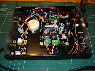
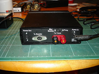
I found a suitable case on Ebay made from black plastic with aluminium end plates and adequate size to take the PCBs and wiring inside.Drilling, cutting and filing all the holes in the aluminium end plates took three evenings to complete. The aluminium plates were then cleaned, sprayed black and lettered with Letraset rub-down lettering, and finished with some clear spray laquer.

Inside the case is the CAN-CMD main circuit board and the CAN-TERM connector kit PCB with two RJ22 sockets. These can be used to plug in a CAN-USB computer interface, or the forthcoming CAN-CAB handheld controller, or to connect to a layout CBus as required.

The one panel has all the CBus related switches and connectors, and the two indicator LEDs. The green LED only lights up if the microcontroller program is running correctly. The Yellow LED lights up when in 'Mini-Booster' mode or flashes when programming locomotives or accessories decoders. The two RJ22 connectors previously mentioned are on this panel, along with two switches. One switches in a bus terminator resistor, required if this unit is at one end of a long Cbus, or used with just a CAN-CAB or CAN-USB. If this unit is connected to a layout CBus that already has terminators fitted then the inbuilt terminator can be switched out. The second switch allows this unit to supply 12V DC to power other CBus items, like the CAN-USB or CAN-CAB. Again, if connected to a layout Cbus that has a separate 12V DC supply, this can be switched out.

The other panel has a socket to connect the power supply, either 12V AC or 15V DC at up to 1 Amp.The screw terminals allow connection to either a programming track or a small layout if using 'Mini-Booster' mode. The mode of this output is controlled by the switch above. The 4-pin mini-Din socket will allow external DCC Boosters (another forthcoming Merg kit) to be attached if more than 1 Amp is required for a layout. The remaining switch controls 12V DC output the the external boosters if required.
