Saturday, 14 November 2020

Freshwater Point Rodding


One job that I had been putting off for too long was fitting dummy point rodding. It needed to be done before I could get on with adding details to the front half of the layout, as it would be too difficult to access where it had to go without causing damage. With an invite to the Ally Palley 2020 exhibition, I really wanted to get it done in time for that. I just managed to complete it before receiving confirmation that the event was cancelled. C'est la vie. Anyway, it has given me time to add further details before any rescheduled exhibition, whenever that might be.


On Freshwater, rodding was only required for a crossover pair of points near the buffer stops, a point and linked trap point at the station throat, and the facing point lock (FPL) with fouling bar protecting the point at the station throat. Hardly anything, really. I had two etches of point rodding, and one of cranks and pulleys, available from the 2mm Scale Association. These were acquired before the better looking system of etches and guitar wire, created by Laurie Adams, was launched. However, on reading up the instructions for this new system, it was clear that Laurie's system should really be installed before any ballasting, or scenic work is attempted. It was hard enough adding the simpler system to Freshwater with ballast and the station platform in place.


The etched nickel silver rodding I had comprised two runs of 7 rods, each about 11cm long, with cross joins where the support rollers would be. This can be cut down to narrower runs. For Freshwater, only three rods leave the signal box, and the longest stretch is only two rods, so I had plenty. I chose to use code 40 bullhead rail to form the roller supports. They would not have the detail of the newer system, but being near the far side of the layout, and suitably weathered, the lack of detail will only show in close-up photos. 


I started by cutting out lengths of triple and double rodding. A length of the code 40 rail was then laid across one of the etched cross joins, the end of the rail lining up with the side edge of the rodding. It was then soldered down, and the rail cut close to the other edge of the rodding with the faithful Xuron cutters. This was repeated, and repeated, and repeated ....


From the signal box, there is a short run of 3 rods across behind the buffer stops to a right angle corner before running along the front of the platform. For the corner, three right angle cranks were soldered to an offcut of etch, with spacer scraps under each crank so they sat at different heights to avoid interfering with each other. This was given a quick spray of grey primer, and glued in place with UV curing glue. This glue was a godsend in this process, as it gave ample chance to adjust the position of items, and hold them in place, but a 4 second blast of the blue light set it firmly in place. I don't think this job would have been possible with either superglue or epoxy resin.


With the cranks in place in the corner, a length of triple rodding was trimmed to length to fit between the signal box and the cranks, and the rods at the end next to the cranks gently bent to match the different levels of the three cranks. The rodding was then positioned, and glued with more UV glue, one support at a time. This was not easy in the cramped space between the buffer stops, platforms faces and signal box, but it was satisfying once done, and proved that it was worth while completing the job. There is also a pulley for a signal wire to a ground signal guarding the crossover, but I am not sure I will find anything small enough to represent the wire.


 The next run was to the two points for the crossover. This required joining three lengths of rodding, by carefully soldering the ends with a small overlap. One rod connects to both points of the crossover, so a short length of a single rod was soldered underneath one of the triple rods, gently bent down to reach a right angle crank. This should be one of the adjustable cranks. This crank was soldered to another etch offcut to form its base. The third rod was then cut to length for the position of a second adjustable crank further along the platform. This delicate lacework was then glued down, one support at a time, with the UV glue. Short lengths of nickel silver rod were then glued between the cranks and the points, to give the appearance that they connected to tie bars. 


There then followed a long run of twin rods along the platform edge towards the point at the station approach. About halfway, a pair of compensators needed to be fitted. These convert a pull to a push (or vice versa) and automatically take account of expansion and contraction of the rods as the temperature changes. The expansion of one length of rod that is pushing is cancelled out by the expansion of the second length of rod that is pulling. Clever stuff. 


At the far end of the run, one rod is linked to the point and trap point, similar to the crossover, while the remaining rod continues on alone to operate the FPL, with a fouling bar preventing operation of the lock when a vehicle is on it. The rod to the trap point had to have extra cranks as the rod crossing the tracks needed to thread through the point timbers ahead of the trap point blade.


Of course, I ran out of etch with a couple of inches left to complete, and a quick order to the 2mm Scale Association for another etch had to made. 


It was formed from odd bits and pieces to roughly resemble the real thing. 


A final touch was adding manual point levers to the rest of the goods yard points. I also read up about how they work in real life, which is fascinating, and again, clever stuff.


Mostly the rodding is out of the way of the track cleaner. It is just part of the FPL that is slightly above rail level. The manual point levers are a different matter. I place inverted plastic shot glasses over them while I work on the layout, but have demolished and replace two already. 


Friday, 6 November 2020

Adding a few details to Freshwater

I have not been keeping up the blog here, so this is a little belated.

With the CMRA Stevenage exhibition approaching in January 2020, I was busy adding some detail bits to the rear half of the layout, while it was still accessible, before starting on the foreground stuff.

The figures are mostly ModelU, except where noted.

The newsagent now has a browsing customer, matching the photo of the real thing that I have. 


The old git on the bench is a 3D scan of me. 


 Some army guys, possibly connected with the rocket testing base that is about to be constructed nearby, have dropped down from the lorry and are slipping in the rear entrance on their way to some well-earned R&R. These are Gramodels white metal figures. 


A couple of suspicious looking train spotters 


I had this 3D printed by Shapeways, but for some reason the small letters F, T, L and Y did not get past Shapeways error checking. I now have a reprinted sign someone kind produced for me that I will fit when I find the time.


I have also added point levers in the goods yard, and a shunter to operate them. I do not know how long they will last as I have already demolished two of them and had to replant them.


 The bus conductor is selling tickets for the trip to Alum Bay.


Meanwhile, the station master is checking tickets and looking at his watch to see how long it will be before the next train. It could be a long wait, the way we operate the layout. The conifer appears in many photos and a video of the station, so had to be modelled. It was formed from Milliput, and covered in fine turf.  


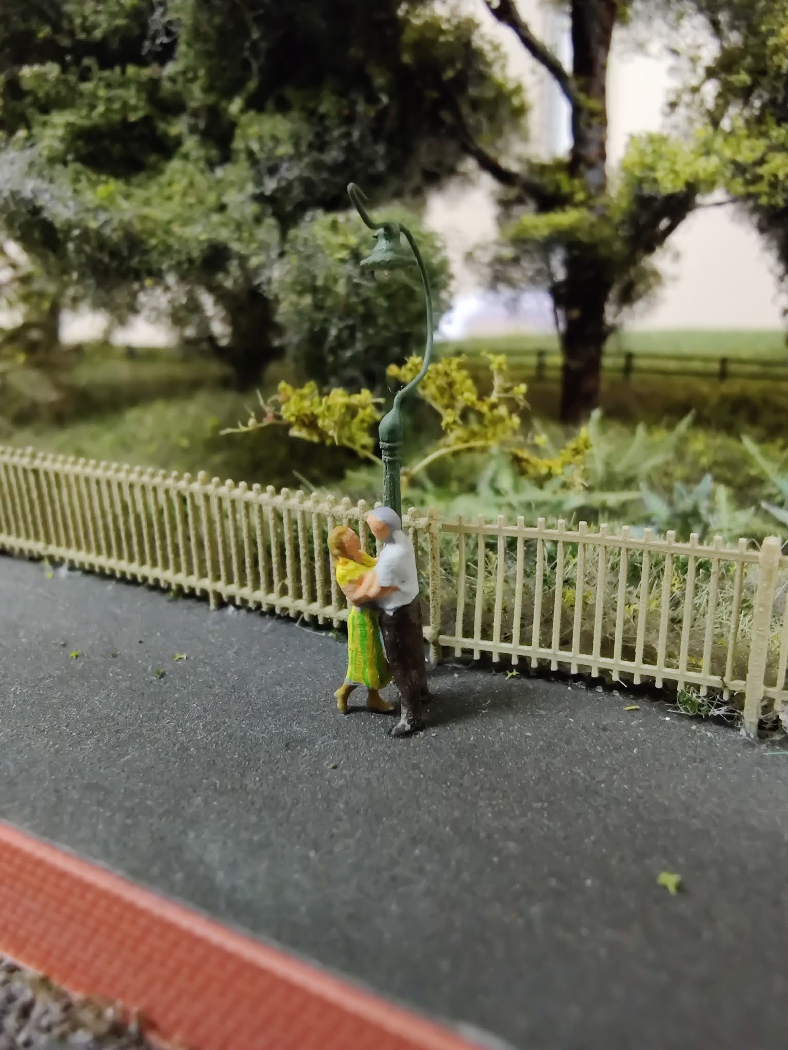
This couple are from Hardies Hobbies. There are now 5 lamps on the platform, of three different styles. The columns and lamps are 3D printed, and the swan necks, or circular necks are 0.3mm nickel-silver rod. 


Luggage in Advance (LIA) was a big feature of traffic on the Island's railways, being delivered to the stations in various vans (including fish vans which prompted many complaints) ready for holiday makers to start their vacation. 


Monday, 14 October 2019

Freshwater at OXRAIL 2019, and a 3rd Terrier

Just shown Freshwater at OXRAIL 2019 in Abingdon. I finally got around to adding some more details to the layout a few weeks before the show, mostly adding further vegetation along the river Yar, and the brook that runs behind the platform.


I had some extra operators, so I managed to just sit and watch shunting operations, for a change. 


And an additional detail added was a pair of benches, a ModelU scan of yours truely, and a terrier, donated to me by Hardy's Hobbies at the Tonbridge show earlier this year. The dog is extremely small. 


Tuesday, 19 February 2019

Like Poles Repel

Another long pause in activity following my participation in the Channel 5 'Great Model Railway Challenge'. Having completed our heat, and then being in the final, we were asked to build another layout for the Radio Times. Then, Peco invited us to have our Santa layout on their stand at Warley, which was followed by a visit to Bognor Regis. Finally, I could get back to worrying about Freshwater, with two shows in February, Stafford and Tonbridge.
 
As reported earlier, I use small 'rare earth' magnets for operating DG couplings. I mounted three magnets on a bar that is moved by a servo so the bar covers three parallel tracks. This gives me 9 uncoupling positions for the cost of 3 servos. However, two positions near the centre of the layout were always a bit temperamental, managing to uncouple some wagons but not others. I put up with this for some time, but for the Stafford show, I had inadvertently left my stock box at home. None of the few odd wagons we had with us would uncouple there, so I had to try to fix the problem before going to Tonbridge.
 
I had checked many times that the magnets were moving to the correct position, centrally below the tracks, so I toyed with the idea of adding a couple more magnets to boost the magnetic field. Then I had a brainwave. This uncoupling position was close to the frog of a point, so two magnets were quite close together. I used another magnet to check, and found that I had one magnet with its north pole on top, and one with its south pole on top. Being so close to each other, the magnetic field was taking a short cut between the magnets instead of going up through the tracks. I turned one of the magnets round, and uncoupling was reliable for the Tonbridge show.
 
It only took me 10 years to rectify this problem.

Sunday, 8 April 2018

Another Deadline Approaches

'Freshwater' will be on show again next Saturday, 14th April 2018. It will be the first 2mmFS layout to be invited to the East Surrey N Gauge Show at St Joseph’s Catholic Primary School, Linkfield Lane, Redhill, Surrey, RH1 1EA. As usual, I wanted to get a bit more completed after its last exhibition, and next on the list was the Newsagents stand and the signal box. The main part of these buildings were 3D printed by Shapeways, as were most of the other structures on the layout. However, for these buildings, there were no suitable etched window frames available from the usual suppliers. There has been a long delay while I plucked up courage to create my own artwork and get some etched by PPD. I was so pleased with the results that I just had to add some interior details and lighting.


Unfortunately, this last view will be almost impossible to see at an exhibition, as it faces the backscene.

The interior of the signal box used some etched parts from Severn Models, and a signalman from ModelU. The log book, mug of tea and telephone were just bits of plastic, and the telephone cord was a hair from my head. I am glad they did not have curly telephone cords back then.


So, not only is the signal cabin in a strange position, behind the buffer stops and low down so that a parked van would block the view of the tracks, but the lever frame is at right angles to the main set of windows.


Still plenty of detail to add in this area, but it was waiting for these buildings to be installed.

Thursday, 22 March 2018

Would you like to see my etchings?

Well, I am really proud of my first attempt at producing artwork for etching. This arrived today from PPD, Special Delivery:
 

It all looks crisp and clear, and, more importantly, the correct size. Here are the window frames for Freshwater signal box (top) and the magazine stand (centre and bottom):


And the solebar overlays for the LBSCR 4 wheel carriages:


And finally, some fold-up buffer beams and the guard's lower steps:
I have actually 3D printed some buffer beams, with buffers and hooks, which I might use instead, though.


Saturday, 17 March 2018

Coach Grabrails and First Etch Attempt

Four little four-wheeler carriages seem to require a lot of grab handles. It took most of an evening just bending and cutting these. I have drilled the coach sides for the lower end to fit into, but the top end will be above the window line, and the door surround is too narrow to drill. Fitting them will be interesting.


I have also, with advice from Andy (2mmSA) and Simon (Merg), completed some artwork for creating an etch. This includes window frames for Freshwater signal box and magazine stand, and solebar overlays and steps for the LBSCR 4 wheelers. I struggled with Draftsight, but eventually produced the front and rear layouts. Then I used the huge piece of AutoCad software called TruView to create the final PDF files. This only runs on 64-bit Windows computers. Both these pieces of software are free. Much to my surprise, PPD accepted the files first time, and reckon they should etch OK. We will see in a week or so. I hope to have them in time so I can complete the signal box and magazine stand for the exhibitions in April (Redhill and Epsom).

I was a bit extravagent in filling the minimum etch size, and created several spare copies of everything in case things went wrong. Next time, I might try to be more efficient.


This is just the front view, so the half etched bits look a little odd.