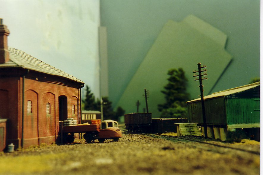
I stumbled across some scanned photos in one of the dusty corners of my hard drive, and thought I would share them. They are of the 2mm finescale layout 'Alresford', built by members of the Basingstoke and North Hants Model Railway Society in the late 1980's. Dave Harris, Clive White, the late John Moffat, and myself were the main driving force behind the production of the layout, although there were others, whose names I have sadly forgotten, that provided some input.
It visited quite a few exhibitions in the first half of the 1990's, and appeared in the Railway Modeller magazine (with better quality photos than these).
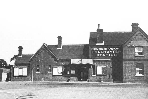
The station building that fronted Freshwater Station from 1889 until it was demolished to make way for a Co-op supermarket, was the largest and grandest of the stations of the Freshwater, Yarmouth and Newport Railway. It comprised the two storey Station Master's house, with single storey booking hall, waiting rooms and conveniences, and was extended at some time to add a parcels office. It was red brick, with tiled roof rather than slates. The brickwork was quite ornate around the eaves and around the division of the two storeys, and an unusual brick bond was used - Flemish Garden Wall Bond. This is formed by 3 stretchers then one header rather than the one stretcher, one header pattern of normal Flemish Bond brickwork. The roof tiles as also not straightforward. There are 5 rows of rectangular tiles, then five rows with scalloped edges, and so forth.
I did not fancy trying to fabricate such an ornate building from card or plastic-card, and as I had been playing with 3D printing, this seemed to be the obvious candidate for my next experiment. In the end, it took a year to complete the 3D model on the computer. Every brick and every tile is a separate 3D object, merged into an inner skeleton of walls. I duplicated rows and areas of bricks and tiles where I could, but it was still a slow and tedious process.
A few test prints of part of the building were purchased from Shapeways to check the proportions, and the details as it progressed. I knew the window frames and ridge tiles were beyond the current abilities of 3D printing, so I made the window apertures to suit some etched brass sash window frames available from Brassmasters, and made a groove at the top of the roofs that an etch from Scalelink fitted. The notice boards have been added from the Trackside Signs range, but apart from that, and a little paint, the building is exactly as it was delivered from Shapeways. The brick and tilework has been rendered crisply and clearly on three sides. The side that is not so good is, of course, the side that is facing the public on the layout.
Well, I didn't give up. At the end of the last post, I had the chassis running nicely with the controller wired directly to the motor, but picking up from the rails was less impressive, despite the fitting of the 'Simpson spring pickups' rubbing on all the axles. The chassis was disassembled and re-assembled a few times, to no avail, and another crank pin came loose from a wheel and had to be re-soldered back in. Quartering the wheels was trickier as the motor was now solidly in place, but plenty of trial and error had the chassis running smoothly again each time.
At the same time, I was working on fitting the Dapol footplate to the chassis. As my version of the Terrier has sandboxes above the footplate, the sandboxes below the footplate were sawn, cut and filed away. If the under footplate sandboxes are to be retained, a little must be removed from behind them as the replacement chassis is slightly wider than the Dapol one. The photo shows the Dapol footplate with motor, the footplate with the motor and cage removed, and finally the footplate with some bits cut away to make room for the new motor to pass through it.
I also had to file a little plastic behind one of the front splashers to clear a gear, and a little from the front edge of the cab floor to clear the rear wheel flanges. Other than that, it fits the chassis, but the wheels will not go round because of the steps. I did not want to lose these nicely moulded features, and it seemed like there should be just enough clearance, but it did mean removing the bosses from the ends of the con rods and cutting the crank pins down to the very minimum. The centre cranks are fine, but the wire insulation was not enough to keep the con-rods in position on the short crank pins, so I had to solder washers onto the centre crank pins to keep the rods firmly in place. The loco body fits without any alteration, which was a bonus. There is even room in the tanks on each side of the motor to add some extra weight.
As I was getting no improvement in pick-up with each rebuild, I decided to resort to adding phosphor-bronze wipers bearing on the tops of the wheel treads. I used the remains of the Dapol pickups to produce these, and soldered them directly to the chassis. Again, there was no improvement. It seemed that the wheels just did not want to make good contact with the rails, and the pickups were removed again as they got in the way of fiting the footplate.
So, as a last resort, I followed Jerry Clifford's advice and made up a pair of rail skids. I had a sheet of .4mm phosphor-bronze which I cut and filed to shape, forming two long arms, with a kink near one end, bent to form the skids. I added another 180 degree bend at the other end in order to produce the most flexible springing possible. The ends were soldered to the bottom chassis stretcher plates.
Success. I finally had a chassis that ran slowly and smoothly on my short test track without stalling. I was so pleased, I threw caution to the wind and fitted the DCC decoder. This is a CT DCX75 which stands upright in the cab. It is hard to see it edge on, and will be completely masked when I eventually fit the crew.
The results I have captured on video. Hopefully the photos will explain everything. I will probably replace one of the skids, as the part that touches the rail is a little too short and seems to catch on some rail joints and on points.
Still to do, add couplings, touch up the chassis paintwork, think about adding the brakes, add the crew, then get on with my other two Terriers.
Since the retirement of '70K Coley Park', and the moving away of most of the group members, the Basingstoke Area Group has languished for a while. However, we now have a couple of new members, and a start has been made on a new group layout, designed by Peter, called 'Camford Junction'*. The initial phase of the layout will comprise a double track main line with a double track secondary line diverging from it, both being at a higher level towards the back of the layout. In the foreground, at the lower level will be a Traction Maintenance Depot (TMD) and a DMU stabling yard. The layout will be set in the last days of British Rail, just before privatisation.
Following a couple of tutorial evenings, the new members, Clive and Robin, have been busy building 1:6 Easitrac points for use in the TMD and yard. The main lines will use flat-bottom rail, so the 1:8 crossover points have been built by me (Ian) using copper-clad sleepers.
The first crossover and some lengths of the secondary line tracks have now been laid. Note the use of some old, and heavy, flourescent light ballast units that are used to hold the track down while the Easitrac glue sets. Also, some paper is used beneath the copper-clad sleepers to bring the rails to the same height as the plain Easitrac sleepers.
* The name Camford is an alternative portmanteau to Oxbridge.